In this tutorial, we shall take a look at EtherChannel which is also known as Link Aggregation or Port-Channel Aggregation. EtherChannel or Link Aggregation is technology which allows us to group multiple physical interfaces to create one logical interface for the purpose of fault tolerance and high throughput links between switches, routers and servers.
What is the difference between Port-Channel & EtherChannel?
As discussed above, EtherChannel is the technology which allows you to group multiple physical interface to create single logical interface. Now that single logical interface is called Port-Channel Aggregation in Cisco terminology or if you are using Juniper Junos then this interface is called LAG (Link Aggregation Group). You can port-channel by grouping maximum of 8 physical links.
What are the types of EtherChannel?
There are 3 methods to configure EtherChannel in your network: the PAgP and LACP negotiating protocols, or Static mode.
Two common link aggregation protocols are Link Aggregation Control Protocol (LACP) and Port Aggregation Protocol (PAgP).
•PAgP is Cisco proprietary and was developed first.
•LACP was created as an open industry standard.
•All the member links must participate in the same protocol on the local and remote switches.
Guidelines to setup EtherChannel without Problems
EtherChannel has some specific guidelines that must be followed in order to avoid configuration problems.
1) All Ethernet interfaces support EtherChannel up to a maximum of eight interfaces with no requirement that the interfaces be on the same interface module.
2) All interfaces within an EtherChannel must operate at the same speed and duplex.
3) EtherChannel links can function as either single VLAN access ports or as trunk links between switches.
4) All interfaces in a Layer 2 EtherChannel must be members of the same VLAN or be configured as trunks.
5) If configured as trunk links, Layer 2 EtherChannel must have the same native VLAN and have the same VLANs allowed on both switches connected to the trunk.
6) When configuring EtherChannel links, all interfaces should be shutdown prior to beginning the EtherChannel configuration. When configuration is complete, the links can be re-enabled.
7) After configuring the EtherChannel, verify that all interfaces are in the up/up state.
8) It is possible to configure an EtherChannel as static, or for it to use either PAgP or LACP to negotiate the EtherChannel connection. The determination of how an EtherChannel is setup is the value of the channel-group number mode command. Valid values are:
active: LACP is enabled unconditionally
passive: LACP is enabled only if another LACP-capable device is connected.
desirable: PAgP is enabled unconditionally
auto: PAgP is enabled only if another PAgP-capable device is connected.
on: EtherChannel is enabled, but without either LACP or PAgP.
9) LAN ports can form an EtherChannel using PAgP if the modes are compatible. Compatible PAgP modes are:
desirable => desirable
desirable => auto
If both interfaces are in auto mode, an EtherChannel cannot be formed.
10) LAN ports can form an EtherChannel using LACP if the modes are compatible. Compatible LACP modes are:
active => active
active => passive
If both interfaces are in passive mode, an EtherChannel cannot form using LACP.
11) Channel-group numbers are local to the individual switch. Although this activity uses the same Channel-group number on either end of the EtherChannel connection, it is not a requirement. Channel-group 1 (interface po1) on one switch can form an EtherChannel with Channel-group 5 (interface po5) on another switch.
EtherChannel Configuration
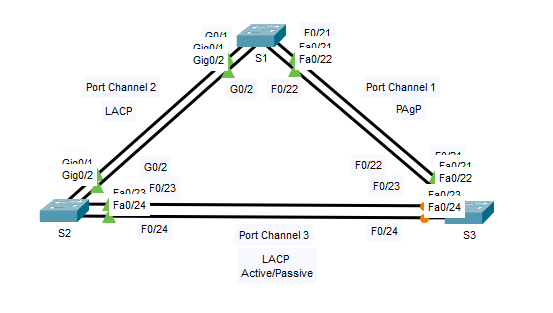
Lets take following topology and understand EtherChannel by configuration.
Part 1: Configure Basic Switch Settings
a. Assign each switch a hostname according to the topology diagram.
b. Before beginning the link aggregation between switches, verify the existing configuration of the ports that connect the switches to ensure that the ports will successfully join the EtherChannels. Commands that provide information about the state of the switch ports include:
Open configuration window
| S1# show interfaces | include Ethernet S1# show interface status S1# show interfaces trunk |
c. Configure all ports that are required for the EtherChannels as static trunk ports.
Close configuration window
Note: If the ports are configured with DTP dynamic auto mode, and you do not set the mode of the ports to trunk, the links do not form trunks and remain access ports. The default mode on a 2960 switch is for DTP to be enabled and set to dynamic auto. DTP can be disabled on interfaces with the switchport nonegotiate command.
Part 2: Configure an EtherChannel with Cisco PAgP
Note: When configuring EtherChannels, it is recommended to shut down the physical ports being grouped on both devices before configuring them into channel groups. Otherwise, EtherChannel Misconfig Guard may place these ports into err-disabled state. The ports and port channels can be re-enabled after EtherChannel is configured.
Step 1: Configure Port Channel 1.
a. The first EtherChannel that is created for this activity aggregates ports F0/21 and F0/22 between S1 and S3. Configure the ports on both switches as static trunk ports.
Open configuration window
b. Use the show interfaces trunk command to ensure that you have an active trunk link for those two links, and the native VLAN on both links is the same.
| S1# show interfaces trunk Port Mode Encapsulation Status Native vlan F0/21 on 802.1q trunking 1 F0/22 on 802.1q trunking 1 G0/1 on 802.1q trunking 1 G0/2 on 802.1q trunking 1 <output omitted> |
c. On S1 and S3, add ports F0/21 and F0/22 to Port Channel 1 with the channel-group 1 mode desirable command. The mode desirable option enables the switch to actively negotiate to form a PAgP link. Note: Interfaces must be shutdown before adding them to the channel group.
| S1(config)# interface range f0/21 – 22 S1(config-if-range)# shutdown S1(config-if-range)# channel-group 1 mode desirable S1(config-if-range)# no shutdown S3(config)# interface range f0/21 – 22 S3(config-if-range)# shutdown S3(config-if-range)# channel-group 1 mode desirable S3(config-if-range)# no shutdown |
The message “Creating a port-channel interface Port-channel 1” should appear on both switches when the channel-group is configured. This interface designation will appear as Po1 in command output.
d. Configure the logical interface to become a trunk by first entering the interface port-channel numbercommand and then the switchport mode trunk command. Add this configuration to both switches.
| S1(config)# interface port-channel 1 S1(config-if)# switchport mode trunk S3(config)# interface port-channel 1 S3(config-if)# switchport mode trunk |
Step 2: Verify Port Channel 1 status.
a. Issue the show EtherChannel summary command on S1 and S3 to verify that EtherChannel is working on both switches. This command displays the type of EtherChannel, the ports utilized, and the port states. Command output is shown for S1.
| S1# show etherchannel summary Flags: D – down P – in port-channel I – stand-alone s – suspended H – Hot-standby (LACP only) R – Layer3 S – Layer2 U – in use f – failed to allocate aggregator u – unsuitable for bundling w – waiting to be aggregated d – default port Number of channel-groups in use: 1 Number of aggregators: 1 Group Port-channel Protocol Ports ——+————-+———–+—————————————- 1 Po1(SU) PAgP F0/21(P) F0/22(P) |
b. If the EtherChannel does not come up, shut down the physical interfaces on both ends of the EtherChannel and then bring them back up again. The show interfaces trunk and show spanning-tree commands should show the port channel as one logical link.
Close configuration window
Also Read:
Part 3: Configure an 802.3ad LACP EtherChannel
Step 1: Configure Port Channel 2.
a. In 2000, the IEEE released 802.3ad, which is an open standard version of EtherChannel. It is commonly referred to as LACP. Using the previous commands, configure the link between S1 and S2, using ports G0/1 and G0/2, as an LACP EtherChannel. You must use a different port channel number on S1 than 1, because you already used that in the previous step. To configure port channel 2 as LACP, use the interface configuration mode channel-group 2 mode active command. Active mode indicates that the switch actively tries to negotiate that link as LACP, as opposed to PAgP. The configuration of S1 is shown below.
Open configuration window
| S1(config)# interface range g0/1 – 2 S1(config-if-range)# shutdown S1(config-if-range)# channel-group 2 mode active S1(config-if-range)# no shutdown S1(config-if-range)# interface port-channel 2 S1(config-if)# switchport mode trunk |
Step 2: Verify Port Channel 2 status.
Use the show commands from Part 1 Step 2 to verify the status of Port Channel 2. Look for the protocol used by each port.
Part 4: Configure a Redundant EtherChannel Link
Step 1: Configure Port Channel 3.
There are various options for the channel-group numbermode command:
| S2(config)# interface range f0/23 – 24 S2(config-if-range)# channel-group 3 mode ? active Enable LACP unconditionally auto Enable PAgP only if a PAgP device is detected desirable Enable PAgP unconditionally on Enable Etherchannel only passive Enable LACP only if a LACP device is detected |
a. On switch S2, add ports F0/23 and F0/24 to Port Channel 3 with the channel-group 3 mode passive command. The passive option indicates that you want the switch to use LACP only if another LACP device is detected. Statically configure Port Channel 3 as a trunk interface.
| S2(config)# interface range f0/23 – 24 S2(config-if-range)# shutdown S2(config-if-range)# channel-group 3 mode passive S2(config-if-range)# no shutdown S2(config-if-range)# interface port-channel 3 S2(config-if)# switchport mode trunk |
b. On S3, add ports F0/23 and F0/24 to Port Channel 3 with the channel-group 3 mode active command. The active option indicates that you want the switch to use LACP unconditionally. Statically configure Port Channel 3 as a trunk interface.
Step 2: Verify Port Channel 3 status.
a. Use the show commands from Part 1 Step 2 to verify the status of Port Channel 3. Look for the protocol used by each port.
b. Creating EtherChannel links does not prevent Spanning Tree from detecting switching loops. View the spanning tree status of the active ports on S1.
| S1# show spanning-tree active VLAN0001 Spanning tree enabled protocol ieee Root ID Priority 32769 Address 0001.436E.8494 Cost 9 Port 27(Port-channel1) Hello Time 2 sec Max Age 20 sec Forward Delay 15 sec Bridge ID Priority 32769 (priority 32768 sys-id-ext 1) Address 000A.F313.2395 Hello Time 2 sec Max Age 20 sec Forward Delay 15 sec Aging Time 20 Interface Role Sts Cost Prio.Nbr Type —————- —- — ——— ——– ——————————– Po1 Root FWD 9 128.27 Shr Po2 Altn BLK 3 128.28 Shr |
Port Channel 2 is not operative because Spanning Tree Protocol placed some ports into blocking mode. Unfortunately, those ports were the Gigabit ports. In this topology, you can restore these ports by configuring S1 to be primary root for VLAN 1. You could also set the priority to 24576.
S1(config)# spanning-tree vlan 1 root primary
or
S1(config)# spanning-tree vlan 1 priority 24576
Close configuration window
You may have to wait for STP to recalculate the tree topology. Press fast-forward if necessary. Use the show spanning-tree active command to verify that the Gigabit ports are now in the forwarding state.
That’s all for now, in this article we developed our understanding EtherChannel and configure LAB for EtherChannel. I hope this has been informative for you, if you like this, kindly share it on facebook and other social media platforms to support us.