In our previous article on OSPF Introduction, we have explained why we need OSPF areas and in another article we learnt how to configure basic single area OSPF configuration. In this article we shall learn how you can configure multi area OSPF.
We shall be using following network topology for OSPF multi-area OSPF configuration.
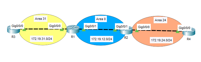
OSPF multi-area topology explaination
Above we have R1 and R2 in OSPF Area 0 (backbone area), Between R1 and R3 we have area 13 and between R2 and R4 we use OSPF area 24. Also we have loopback interfaces lo0 configured on R3 and R4 having IP addresses 3.3.3.3 & 4.4.4.4 respectively.
OSPF Multi-area Configuration
So lets start from Routers R1 and R2 and see how OSPF is configured between these routers. We shall start with OSPF network commands to advertise our networks into OSPF domain.
#R1 Area 0 Configuration
router ospf 1

 network 172.19.12.0 0.0.0.255 area 0
#R2 Area 0 Configuration
router ospf 1
 network 172.19.12.0 0.0.0.255 area 0
Now lets configure R1 and R3 for OSPF area 31
#R1 Area 31 Configuration
router ospf 1
 network 172.19.31.0 0.0.0.255 area 31
#R3 Area 31 Configuration
router ospf 1
 network 172.19.31.0 0.0.0.255 area 31
 network 3.3.3.3 0.0.0.0 area 31
Now lets configure R2 and R4 for OSPF area 24
#R2 Area 24 Configuration
router ospf 1
 network 172.19.24.0 0.0.0.255 area 24
#R4 Area 24 Configuration
router ospf 1
 network 172.19.24.0 0.0.0.255 area 24
 network 4.4.4.4 0.0.0.0 area 24
That’s it, we have configured our topology with OSPF multi-area. Now lets verify our OSPF neighborships on all OSPF routers.
R1#show ip ospf neighbor


Neighbor ID     Pri   State       Dead Time   Address         Interface
2.2.2.2           1   FULL/DR     00:00:37    172.19.12.2     GigabitEthernet0/0/1
3.3.3.3           1   FULL/DR     00:00:37    172.19.31.3     GigabitEthernet0/0/0
R1 has formed OSPF neighborships with R2 and R3, we have used the command “show ip ospf neighbor” to check the OSPF neighborships. Now lets check R2 OSPF neighborships.
R2#show ip ospf neighbor


Neighbor ID     Pri   State       Dead Time   Address         Interface
1.1.1.1           1   FULL/BDR    00:00:32    172.19.12.1     GigabitEthernet0/0/1
4.4.4.4           1   FULL/DR     00:00:32    172.19.24.4     GigabitEthernet0/0/0
Now lets verify our routing tables by using command “show ip route ospf”.
R1#show ip route ospf
     3.0.0.0/32 is subnetted, 1 subnets
O       3.3.3.3 [110/2] via 172.19.31.3, 00:30:40, GigabitEthernet0/0/0
     4.0.0.0/32 is subnetted, 1 subnets
O IA    4.4.4.4 [110/3] via 172.19.12.2, 00:30:35, GigabitEthernet0/0/1
     172.19.0.0/16 is variably subnetted, 5 subnets, 2 masks
O IA    172.19.24.0 [110/2] via 172.19.12.2, 00:30:35, GigabitEthernet0/0/1
Lets discuss above routing table, on R1 routing table we have 3.3.3.3 OSPF route marked as “O” which means OSPF Intra-area route, the loopback interface of R3 router. Next, we have two OSPF routers marked as “IA” which means inter-area routes. R2 will also have similar output lets verify.
R2#show ip route ospf
     3.0.0.0/32 is subnetted, 1 subnets
O IA    3.3.3.3 [110/3] via 172.19.12.1, 00:45:42, GigabitEthernet0/0/1
     4.0.0.0/32 is subnetted, 1 subnets
O       4.4.4.4 [110/2] via 172.19.24.4, 00:45:47, GigabitEthernet0/0/0
     172.19.0.0/16 is variably subnetted, 5 subnets, 2 masks
O IA    172.19.31.0 [110/2] via 172.19.12.1, 00:45:42, GigabitEthernet0/0/1
R2 is also having two inter-area OSPF routes and one Intra-Area OSPF route from R4 loopback interface having IP 4.4.4.4. Now lets check R3 and R4 routing tables.
R3#show ip route ospf
     4.0.0.0/32 is subnetted, 1 subnets
O IA    4.4.4.4 [110/4] via 172.19.31.1, 00:48:52, GigabitEthernet0/0/0
     172.19.0.0/16 is variably subnetted, 4 subnets, 2 masks
O IA    172.19.12.0 [110/2] via 172.19.31.1, 00:49:02, GigabitEthernet0/0/0
O IA    172.19.24.0 [110/3] via 172.19.31.1, 00:48:52, GigabitEthernet0/0/0
R4#show ip route ospf
     3.0.0.0/32 is subnetted, 1 subnets
O IA    3.3.3.3 [110/4] via 172.19.24.2, 00:50:45, GigabitEthernet0/0/0
     172.19.0.0/16 is variably subnetted, 4 subnets, 2 masks
O IA    172.19.12.0 [110/2] via 172.19.24.2, 00:50:55, GigabitEthernet0/0/0
O IA    172.19.31.0 [110/3] via 172.19.24.2, 00:50:45, GigabitEthernet0/0/0
R3 & R4 are receiving all routes as Inter-Area marked as “O IA”. Now one last thing, lets verify the connectivity between R3 and R4 loopback interfaces, which should work fine as both routers are receiving OSPF routes.
R3#ping 4.4.4.4

Type escape sequence to abort.
Sending 5, 100-byte ICMP Echos to 4.4.4.4, timeout is 2 seconds:
!!!!!
Success rate is 100 percent (5/5), round-trip min/avg/max = 0/0/0 ms
That’s it. the OSPF multi-area topology configurations are successful and verified. Now its your time to practice OSPF multi-area in Cisco Packet tracer, for your ease i have pasted all the configurations below.
R1 Configuration
hostname R1
interface GigabitEthernet0/0/0
 ip address 172.19.31.1 255.255.255.0
 duplex auto
 speed auto
!
interface GigabitEthernet0/0/1
 ip address 172.19.12.1 255.255.255.0
 duplex auto
 speed auto
!
router ospf 1
 router-id 1.1.1.1
 log-adjacency-changes
 network 172.19.12.0 0.0.0.255 area 0
 network 172.19.31.0 0.0.0.255 area 31
R2 Configuration
hostname R2
interface GigabitEthernet0/0/0
 ip address 172.19.24.2 255.255.255.0
 duplex auto
 speed auto
!
interface GigabitEthernet0/0/1
 ip address 172.19.12.2 255.255.255.0
 duplex auto
 speed auto
!
router ospf 1
 router-id 2.2.2.2
 log-adjacency-changes
 network 172.19.12.0 0.0.0.255 area 0
 network 172.19.24.0 0.0.0.255 area 24
Also Read
R3 Configuration
hostname R3
interface Loopback0
 ip address 3.3.3.3 255.255.255.255
!
interface GigabitEthernet0/0/0
 ip address 172.19.31.3 255.255.255.0
 duplex auto
 speed auto
!
router ospf 1
 router-id 3.3.3.3
 log-adjacency-changes
 network 172.19.31.0 0.0.0.255 area 31
 network 3.3.3.3 0.0.0.0 area 31
R4 Configuration
hostname R4
interface Loopback0
 ip address 4.4.4.4 255.255.255.255
!
interface GigabitEthernet0/0/0
 ip address 172.19.24.4 255.255.255.0
 duplex auto
 speed auto
!
router ospf 1
 router-id 4.4.4.4
 log-adjacency-changes
 network 172.19.24.0 0.0.0.255 area 24
 network 4.4.4.4 0.0.0.0 area 24
Conclusion
In this article we learnt how to configure OSPF multi-area using Cisco Packet Tracer topology. Also we have verified OSPF routes from different OSPF area.